6 Setting up your Raspberry Pi Devices
As we reviewed in the previous chapter, there are a myriad of sensors available out there that can help us enact the sensing infrastructure needed to create more autonomous buildings. These sensors, however, need to interface with some computing device before they can be useful to the second part of the sense, plan and act trifecta for any autonomous system. In this chapter, we will review and configure two platforms that can be used for this purpose, both designed and developed by the Raspberry Pi Foundation, namely:
- The Rasbperry Pi 4 Model B, from here on abbreviated as RPi 4.
- The Raspberry Pi Pico W, from here on abbreviated as RPi Pico.
The first of these, is a full single-board-computer (SBC) that has a 40-pin General-Purpose Input/Output (GPIO) port, with which one can communicate with digital transducers or with an external Analog-to-Digital (ADC) converter. The Pico W, on the other hand, is a board served by a custom microcontroller (the RP2040) that is significantly less powerful than the RPi 4 but also significantly less expensive and power-hungry. Depending on the application you have in mind, you may choose either (or both) of these platforms to interface with your sensors. Both of these devices have a wireless radio that allows them to connect to WiFi and be accessible remotely. Both can be programmed using Python (specifically through the help of MicroPython and CircuitPython).
The goal for today is to allow us to obtain measurements from a light intensity sensor (a photoresistor) using both the RPi 4 and the RPi Pico and, along the way, learn how to set up and configure these devices so that you are ready to use them when the time comes.
6.1 A Simple Photoresistor
The sensor that we will try to connect is this simple photoresistor:
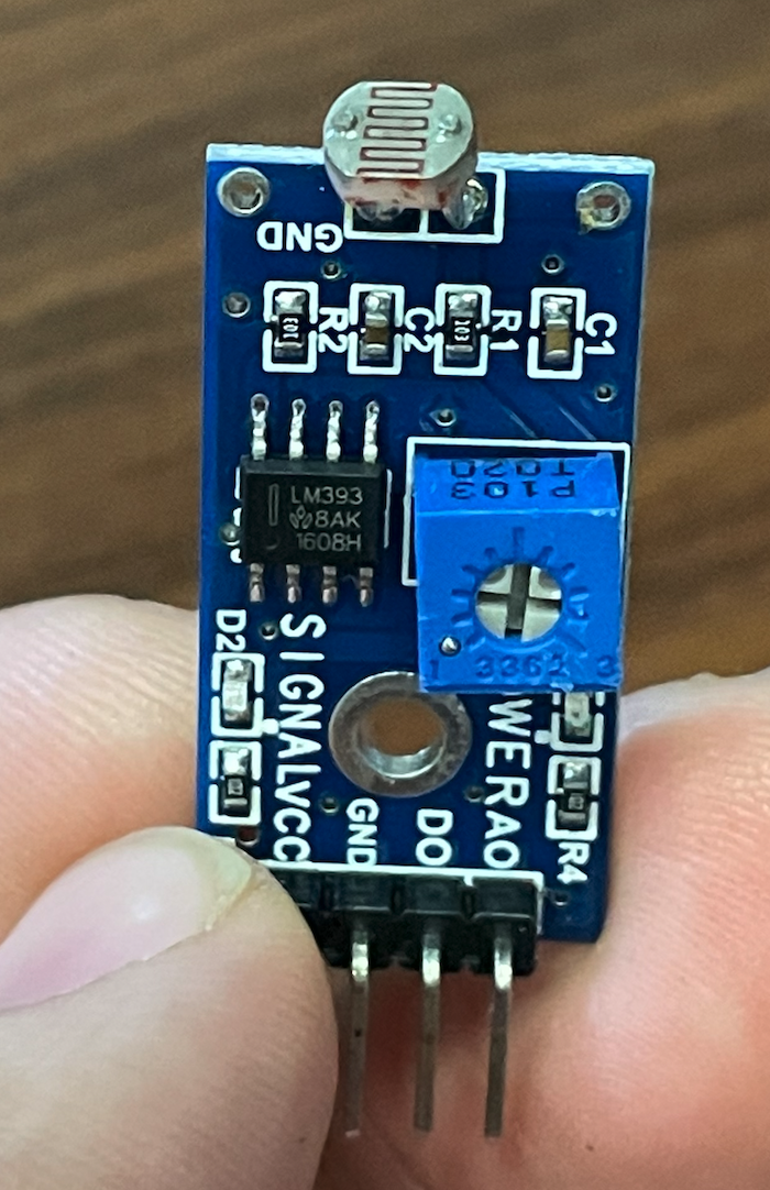
This sensor reacts to light by decreasing its resistance through the principle of photoconductivity. The more light (luminosity) the lower the resisance, and with less light, resistance increases. We can measure the resistance by using Ohm’s law (\(V = IR\)) and, assuming constant current, just measuring the voltage drop across this resistor.
As you can see in the figure, there is much more than just a photoresistor (the actual sensor is just the little thing sticking out on the top). The board also has an ADC, a trimmer potentiometer (trimpot), and other components. For this particular application, we are not interested in any of these and would just like to try to interface with the sensor as directly as possible (receiving the analog electrical voltage drop across the photoresistor). We can do this by focusing on two of the pins at the bottom: AO (Analog Output) and GND (Ground).
6.2 Raspberry Pi 4 Configuration
The RPi 4 does not come with an Analog-to-Digital converter that we can (easily) access. Thus, we’ll need to interface it with an external ADC if we are to sample the raw analog output from the photoresistor. For this reason, before we can finish the task on the RPi 4 we will need to complete two steps: (a) set up the RPi so that it has an operating system (OS), an account we can access it with, and an Internet connection in case we want to access it remotely; and (b) use the GPIO port to interface with an ADC such as the MCP3008.
6.2.1 Setting up the RPi 4
To start, once you open up your RPi 4 kit, you will need to make sure that you have the following items in it (at least):
- A Rapsberry Pi 4 with heat sinks
- A mini-HDMI to HDMI cable
- A microSD card
- A microSD to USB adapter
- A USB-C cable
You will also need access to a USB power supply (your computer can perform that job), an HDMI monitor (at least to start), a keyboard, a mouse and another computer. Once the RPi 4 has been properly configured, you will only need the USB-C cable to power it.
Since these devices have been used before, a good starting point is to reflash the microSD card with a fresh install of the Raspberry Pi Operating System. To do that, follow the instructions here:
Install Raspberry Pi OS using Raspberry Pi Imager
In particular, you will download and load the Raspberry Pi imager, put the microSD card in the USB adapter and connect it to your computer, and follow the screen prompts on the imager to flash Raspberry Pi OS on the card (which will show on your computer in the same way that any externall mass storage device would). This process can take around 30 minutes or so depending on your computer and internet connection.
Once you do that, you can put the SD card back into the Rapsberry Pi’s microSD reader, connect the keyboard, mouse and monitor to it, and power it via the USB-C port. You should be booting up to a new OS. If you installed an old version of the OS then the default username is pi with password raspberry. Otherwise, you will be prompted for a new password.
If it’s all working correctly, you may want to take a moment to connect the device to the Internet. If you are at home, then follow the same procedure you would follow with any computer in your house. If you are on campus, you will need to connect it to the CMU-DEVICE network and, before that, you should register the device using the following website: Device Registration. You will need to provide the MAC address for the Wireless card on your Raspberry Pi. This can be found in many ways, one of which is to issue ifconfig on a terminal in the RPi 4, or inspecting the contents of /sys/class/net/eth0/address (or /sys/class/net/wlan0/address).
6.2.2 Connecting the MCP3008
Let’s follow the instructions here
Alternatively, we could follow instructions for a more modern package called gpiozero here.
6.2.3 Sampling from the photoresistor
The instructions above also include this part. Once the lecture is over, I will transcribe things here.
6.3 Raspberry Pi Pico Configuration
For the Pico, we will follow the instructions here.
6.4 Getting some help
Sometimes no matter how many references you have been provided, you can still get stuck on setting things up especially if it is your first time using these devices. Though I would strongly recommend against blidly trusting the guidance of a Large Language Model (LLM), if you are careful they can be of immense assistance to get you unstuck. For example, I asked ChatGPT o1 for assistance creating a guideline to this whole exercise and this is what it came up with: Raspberry Pi Light Sensing.
6.5 What have you learned?
After the lecture, here are some questions that you may want to try to answer yourself to see if you really understood things.
- What are the differences between the RPi Pico and RPi 4? Give an example of a project for which each one is better suited than the other.
- We used a photoresistor for this example. Are the computing platforms (RPi 4 and RPi Pico) limited to photoresistors only? If not, what are the limitations we should consider when considering other sensors we could use with these platforms?
- Does the RPi 4 have an analog-to-digital converter? If not, what is one way to sample analog signals using the RPi 4?
- What is the clock speed for the RPi Pico and how do you find the answer using the
machineMicroPython module? How is it related to the sampling rate we can achieve for sampling the analog signals with it? - What is the clock speed for the RPi 4, and how do you find out? Is it kept constant? How is it related to the sampling rate we can achieve for sampling analog signals?
- Answered by: John
The RPi 4 does not have a built-in ADC (analog to digital converter), so in order to sample analog signals on the RPi 4, we need an external ADC such as the MCP3008 we used in class. With this, we can connect the analog device to the external ADC, then communicate the converted digital signal to the RPi via another communication method (SPI, I2C, Serial, etc…).